Basic Electronics
Operation of full wave bridge rectifier The full wave bridge rectifier is designed to convert an ...
Operation of full wave bridge rectifier
The full wave bridge rectifier is designed to convert an AC sine-wave to a full-wave pulsating DC signal.
The bridge is normally connected to the secondary of a transformer.
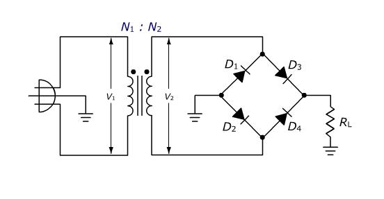
The discussion of the operation of this circuit will be performed using conventional current flow. Current will flow from a point with a higher potential to a point of lower potential. During the positive half cycle you can thing of a circuit being equivalent to the following:

Diode D2,D3 will be forward biased and will conduct current . Diode D1,D4 will be reversed biased and will not conduct current.
During the negative half cycle, you can think of the circuit being equivalent to the following:

Diode D1, D4 will be forward biased and will conduct current. Diode D2, D3 will be reversed biased and will not conduct current, and current will flow through the load.
The output waveform appears as follows:


